Philips SlimStyle 60W LED bulb teardown
While I was visiting Home Depot, I saw a Philips SlimStyle 60W LED bulb on clearance for two-dollars. I could not resist buying it for a tear-down to see how it’s built. I always wondered how they convert the 120VAC to a regulated DC voltage with high-current feed for lighting up those LED’s. So here is the first version of the tear-down showing you what’s inside the bulb. I will blog more about the current and voltage at the LED junction on a subsequent blog.
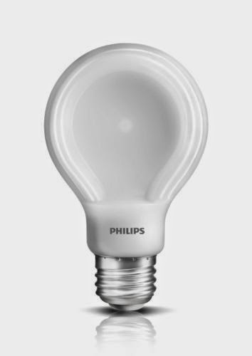
Picture of the bulb before the tear-down. You can see the unique flat shape.
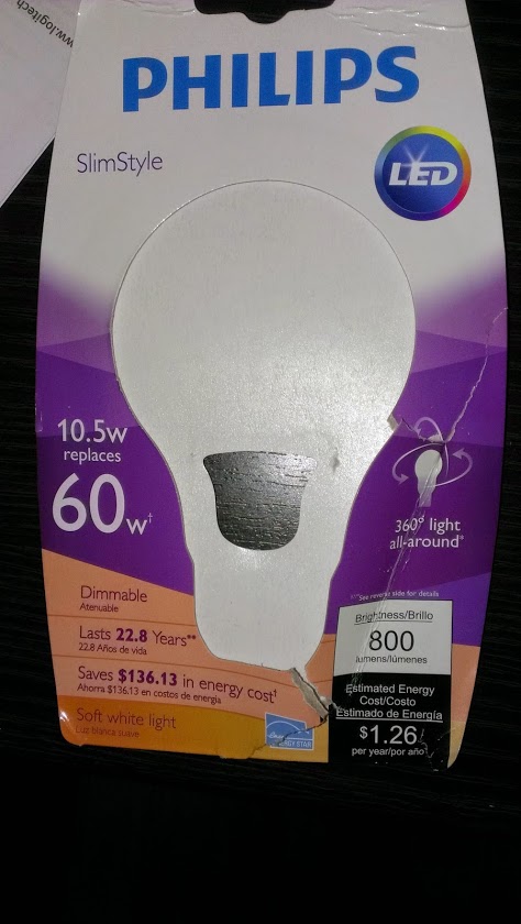
Packaging front
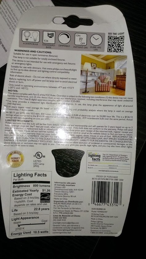
Packaging back
What you expect to find is a custom version of what is called in Electrical Engineering as an LED Driver Circuit (and here). What makes this one interesting is how they made this all fit inside a tiny little base. And the flat design with the beveled plastic aids in efficient heat dissipation. So you don’t see the big metal base you find in other LED bulb models.
Plastic encasing removed (cut using a band-saw)
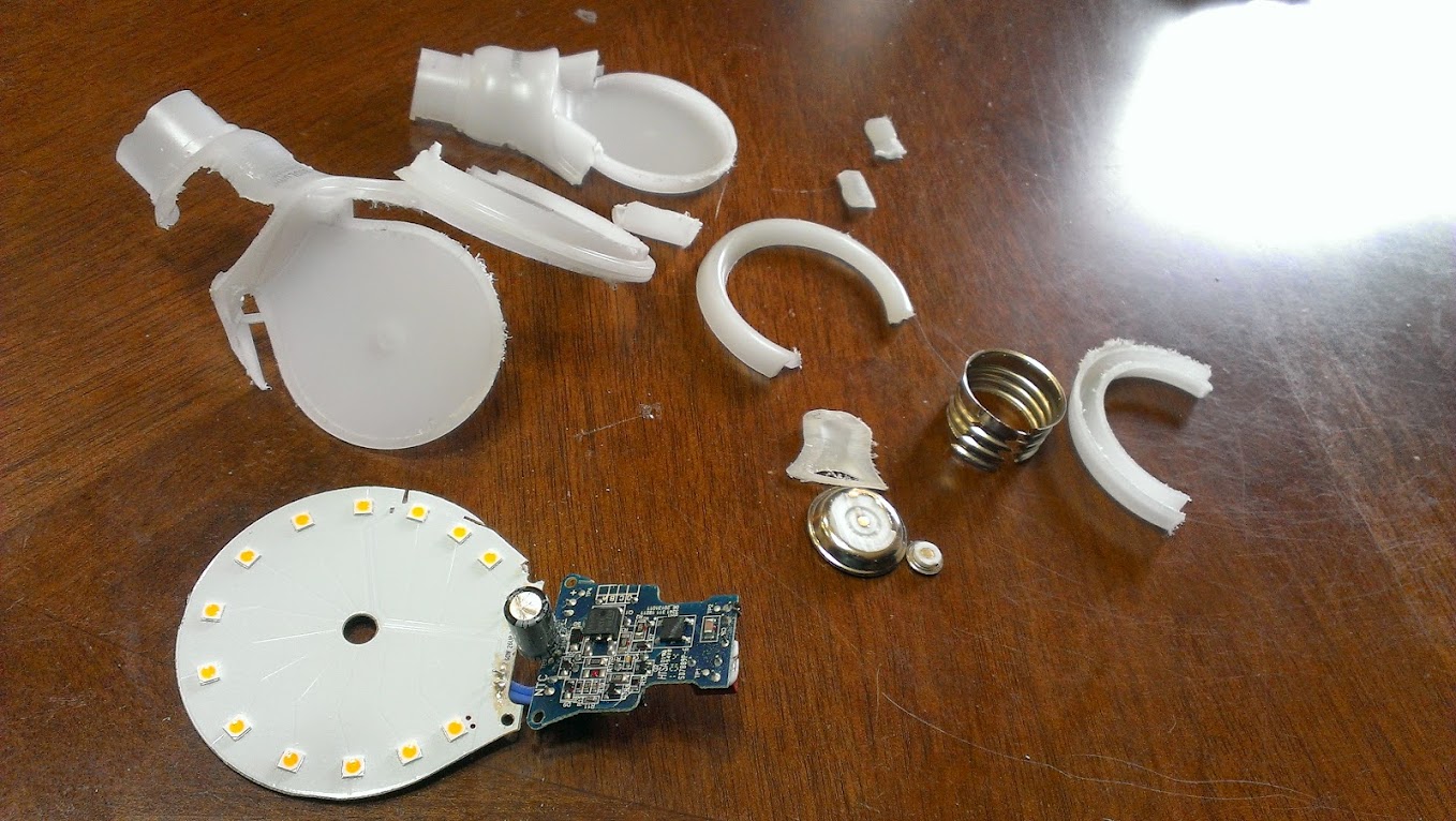
You can see the LED’s placed in a radial manner front and back. Although the placement allows you to distribute the light you still end up with a shadow effect. (I think the incandescent light was the perfect design)
Front face of the PCB board which makes up the base of the bulb:
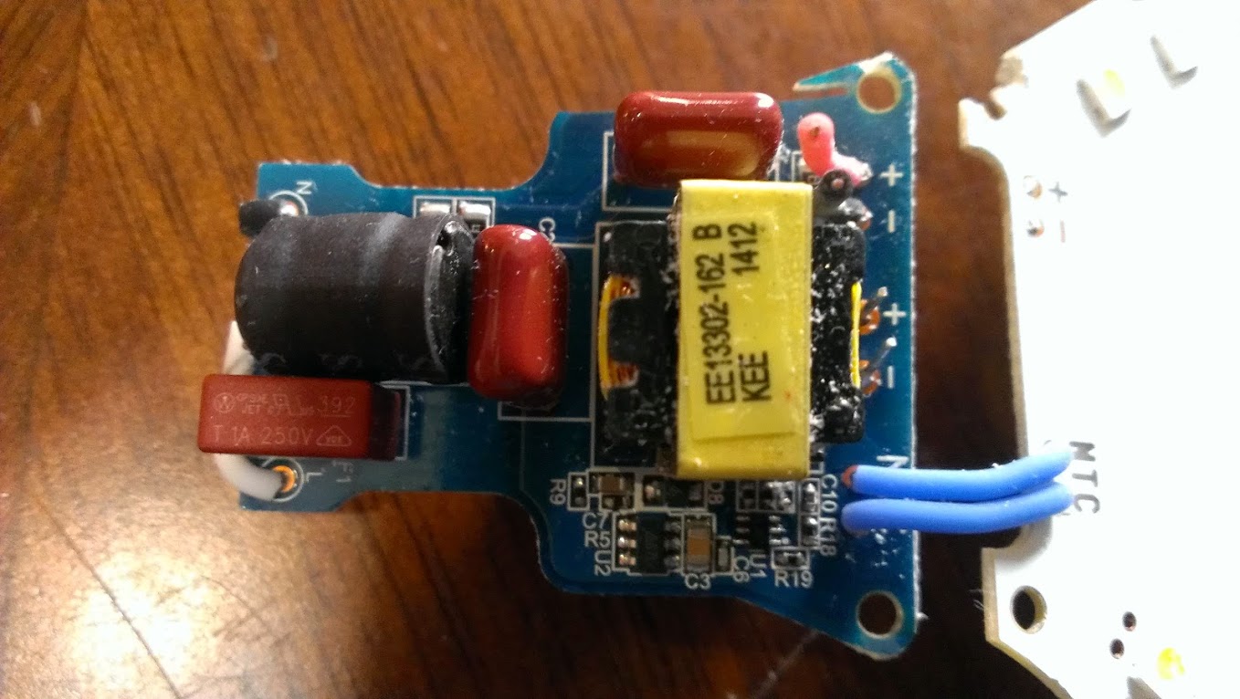
Transformer……….. EE13302-162 B (KEE 1412) (closest neighbor to this transformer)
Black capacitor… S103
Orange rectangular piece bottom left (with Westinghouse logo) is a standard ceramic-fuse.
The black (labeled-N) and white wires (labeled-L) gets soldered to the bulb metallic base (120VAC inputs)
Back of the PCB board:
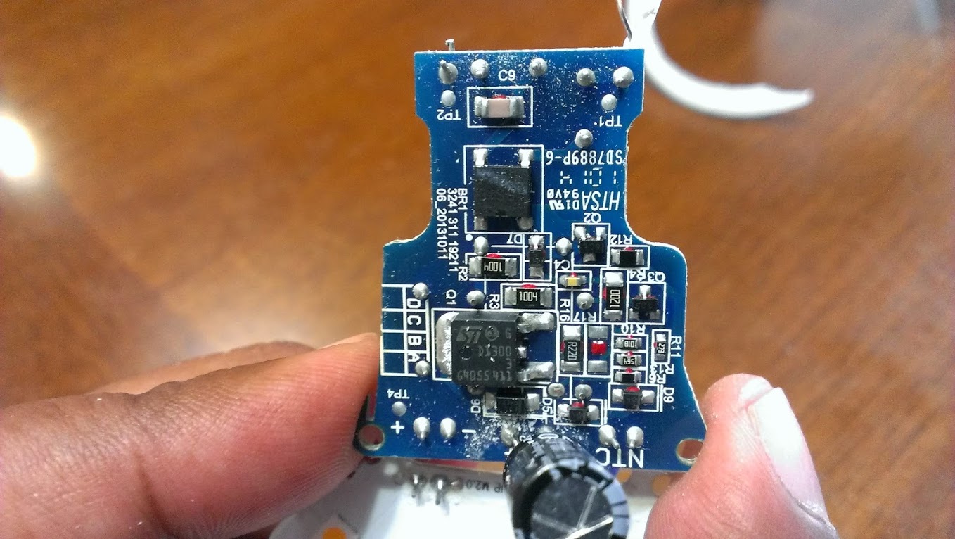
D1300 is a standard NPN transitor.
More to come in the next blogs. Stay tuned.